Understanding Airfoil CFD Simulation: A Beginner's Guide
Understanding Airfoil CFD Simulation: A Beginner’s Guide
Computational Fluid Dynamics (CFD) is an indispensable tool in modern engineering, particularly in aerospace and automotive industries. It allows engineers to predict fluid flow behavior, heat transfer, and related phenomena by solving complex mathematical equations numerically. One of the most fundamental applications of CFD is the simulation of airflow over an airfoil, which is crucial for understanding lift and drag generation in aircraft wings.
What is an Airfoil?
An airfoil is the cross-sectional shape of a wing, blade (of a propeller, rotor, or turbine), or sail (as seen in a sailboat). Its shape is designed to generate aerodynamic force, primarily lift, when moving through a fluid. Key characteristics of an airfoil include its leading edge, trailing edge, chord line, and camber.
The Basics of Airfoil CFD Simulation
Simulating airflow over an airfoil involves several key steps:
- Geometry Definition: Creating the precise shape of the airfoil. Standard airfoils like the NACA series (e.g., NACA 0012, NACA 2412) are often used for benchmark studies.
- Meshing (Grid Generation): Discretizing the fluid domain around the airfoil into a finite number of small cells or elements. The quality and density of the mesh significantly impact the accuracy and computational cost of the simulation. Finer meshes are typically required near the airfoil surface and in regions of high flow gradients (e.g., wake).
- Physics Setup: Defining the fluid properties (e.g., air density, viscosity), boundary conditions (e.g., inlet velocity, outlet pressure, no-slip wall on the airfoil surface), and turbulence models (e.g., RANS models like k-epsilon, k-omega SST).
- Solver Execution: Running the numerical solver to compute the flow field by iteratively solving the Navier-Stokes equations.
- Post-processing: Analyzing and visualizing the simulation results, such as pressure contours, velocity vectors, and streamlines.
Visualizing Airflow: Streamlines
Streamlines are lines that are everywhere tangent to the velocity vector field. They provide a clear visual representation of the fluid flow path. In CFD simulations, streamlines are often colored to indicate various flow properties, such as velocity magnitude or pressure.
Below is an example of a CFD simulation showing airflow streamlines over an airfoil. Notice how the streamlines are denser and change color around the airfoil, indicating variations in velocity.
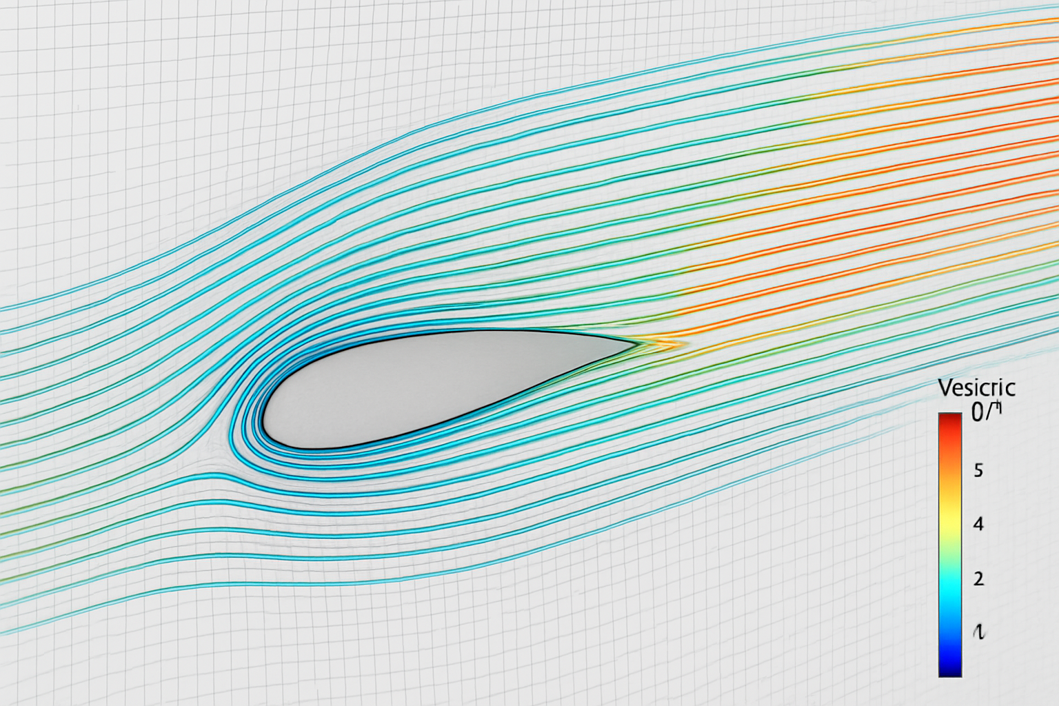
Figure 1: CFD simulation showing velocity streamlines over a NACA 0012 airfoil at a slight angle of attack. Colors indicate velocity magnitude (blue for low, red for high).
Key Concepts Illustrated by the Simulation
- Stagnation Point: At the leading edge of the airfoil, the flow comes to a halt, creating a stagnation point where velocity is zero and pressure is maximum.
- Acceleration over the Upper Surface: The flow accelerates over the curved upper surface of the airfoil, leading to lower pressure and contributing to lift.
- Deceleration under the Lower Surface: The flow decelerates under the flatter lower surface, leading to higher pressure.
- Wake Region: Behind the trailing edge, a wake region forms where the flow is turbulent and characterized by lower velocities and increased mixing.
Turbulence Modeling
For most real-world applications, airflow is turbulent. Turbulence models are crucial for accurately capturing the effects of turbulence without resolving every single eddy, which would be computationally prohibitive. Common RANS (Reynolds-Averaged Navier-Stokes) models include:
- k-epsilon (k-ε): A robust and widely used model, good for general-purpose industrial applications.
- k-omega (k-ω): Often performs better for flows with adverse pressure gradients and boundary layer separation.
- SST (Shear Stress Transport) k-omega: A hybrid model that combines the best features of k-epsilon and k-omega, providing good accuracy for a wide range of flows, including those with separation and reattachment.
Understanding these models and their applicability is vital for setting up accurate CFD simulations.
Conclusion
CFD simulation of airfoils is a foundational topic that helps engineers design more efficient and safer aircraft. By mastering the steps from geometry to post-processing and understanding the underlying fluid dynamics principles, you can unlock the power of CFD to solve complex engineering challenges. Stay tuned for more in-depth tutorials on specific CFD software and advanced techniques!
References:
[1] Anderson, John D. Fundamentals of Aerodynamics. McGraw-Hill Education, 2017. [2] Versteeg, H. K., and W. Malalasekera. An Introduction to Computational Fluid Dynamics: The Finite Volume Method. Pearson Education, 2007. [3] NACA Airfoil Series. NASA Technical Reports Server.